Topside Alignment Placement (TAP) Process
From: Author: Publish time:2021-09-13 15:06 Clicks:0
In CPV applications, TAP option maximizes efficiency and power density and automates assembly of large solar panels. In embedded applications, TAP aligns die top features for high density interconnect on large substrate.

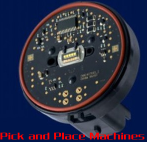
In Automotive applications, accurate LED alignment eliminates the need for a secondary lens, thus reducing component count and overall cost of lamp.
I.C.T is a manufacturer of SMT machines. It mainly provides customers with SMT production lines including SMT Stencil Printers, Pick and place machines, Reflow Oven, AOI Machine, Wave Soldering Machine and PCB Handling Machine etc. I.C.T has more than 25 researches on SMT and DIP technology, for the world Customers provide SMT total solutions. There are successful cases of SMT technICal team in Asia, Europe, AmerICa, AfrICa, and Australia.
More details, please contact us:
Tel: +86 13670124230 (WhatsApp/Skype/WeChat)
Email: etaSMT@foxmail.com
Automotive-Car Headlamp Assembly Options
Topside Alignment Place (TAP) is a process in which the component bottom outline and the active top features are inspected simultaneously by upper and downward looking cameras respectively. The inspection establishes a relationship between the component bottom outline versus the component top patterns. Following top inspection by the downward looking camera (PEC), the component is picked and moved over an upward looking camera (ULC). The upward camera defines the relationship of the component outline to the spindle for placement. The relationship offset from the TAP process is added to the upward camera correction offset for final placement. This process also resolves the issue of component movement between inspect and pick.
The process:
Machine starts by feeding the component to feeder location
The PEC camera locates the programmed topside features on the component. The topside feature referred as the artwork.
The PEC camera locates a reference feature with respect to the artwork
The machine then calculates and stores the artwork‐to‐reference feature offset.
The head picks and scans them over the upward looking camera (ULC). Using ULC, it recognizes the same reference feature use by PEC.
The artwork‐to‐reference feature offset is taken into account in the determination of the final placement location.
The components are then placed on the substrate
The Topside Alignment Place (TAP) can be added to any Fuzion platform; it’s an integrated solution that supports placement of active and passive components on the a single platform.
SMT Off Line AOI, Small SMT Priduction Line, SMT Solder Paste Printing And Reflow Jig, SMT Fully Automatic Stencil Printer, Reflow SMT Oven, Mini Wave Soldering, SMT Machines Fuji, Zuki SMT Machine Fx2, Juki Nozzle SMT Machine, SMT Splicing Machine S906, Shenzhen SMT Soldering Machine, SMT Machine Placement Mechanical Drawings Design, Automatic Optical Inspection PCB, Automated Optical Inspection Manufacturers, AOI PCB Inspection, AOI Inspection Equipment, Xyz Gantry Robot Linear Stage 50MM-4000MM Customizable Ball Screw Linear Guide, Auto Fastening Auto Screw Driving Machine Automatic Fixing Screw Robot

